Mass Airflow Sensors
What is a mass airflow sensor?
A mass airflow sensor (MAF) is used in electronic fuel injection systems on vehicles to measure the amount of air entering the engine so the ECU can determine how much fuel to provide to the engine. The sensor is placed on the intake side of the engine between the air filter and the throttle body. The sensor is sends a an analog or digital signal to the vehicles ECU that is then used to calculate the mass air flow entering the engine.

Types of Mass Airflow Sensors
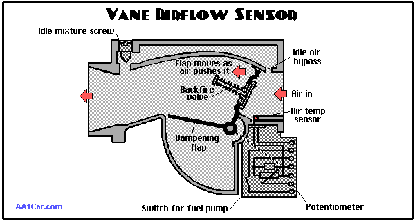
Vane style sensors
A vane style MAF works by having a small, hinged, flap placed in the area of the flow which is connected to a potentiometer. The small flap opens or closes based on the amount of airflow through the sensor which changes the reading of the potentiometer. The signal from the potentiometer is then sent to the ECU to calculate the actual mass air flow entering the engine. In order for the engine to get a true reading of the amount of air entering the engine this airflow sensor must also be used in conjunction with an intake air temperature sensor (IAT). From the reading of the IAT the ECU can calculate the density of the air entering the engine.
Disadvantages of Vane Style MAF
- Not extremely accurate
- Slow responding
- restricts air flow
- must be oriented in certain positions
These disadvantages made the Vane MAF obsolete very quickly

Hot Wire Mass airflow sensor
The most common style of MAF on newer cars is the hotwire sensor. This sensor is very simple because it has no moving parts. A conductive wire is placed within the airflow and a current is passed through it to maintain a temperature. As more air flows over the wire it is cooled and the resistance of the wire decreases. At this point more current flows through the wire to heat it back to an equilibrium temperature. Since this sensor uses the heat transfer properties of air to calculate mass flow it does not require the use of an intake air temperature sensor. The amount of current flowing through the wire is proportional to the amount of air entering the engine. The cars ECU then uses this current value to determine how much fuel is needed. This style of MAF is essentially the same as a hot wire anemometer, only instead of simply measuring wind speed it is used to calculate the actual mass flow through the sensor tube.
The hotwire MAF has several advantages over the vane including, faster response time, improved durability, and it can be placed in any orientation.
Advantages of the hotwire MAF
- Faster response time
- Improved durability
- Can be placed in any orientation
- Doesn't restrict flow
- Not affected by different air pressures. Can be used on super or turbocharged engines

The image shows the "hotwire" placed in the center of the sensor to measure the airflow passing the wire.
"Coldwire" Mass Airflow Sensor
A third, and less common style of MAF is the "coldwire" sensor. This style of sensor is used mainly by General Motors LS series of engines. The main way in which the coldire differs from the hotwire is that it sends out a digital frequency signal as opposed to an analog voltage signal to the engine ECU. It does this by using a small sensor placed in the MAF tube that is part of an oscillator circuit. As more air flows through the tube the inductance of the sensor is changed and therefore the oscillation frequency changes. The ECU reads the change in frequency and is able to calculate the new mass flow rate entering the engine. This style of Airflow sensor shares all of the same advantages of the hotwire style sensor with the only difference being signal type.

This image is of a coldwire MAF for a GM LS3 Engine.
References
http://www.autoshop101.com/forms/h34.pdf
http://www.sensorland.com/HowPage060.html
http://www.ehow.com/how-does_4597355_mass-airflow-sensors-work.html
Comments (0)
You don't have permission to comment on this page.